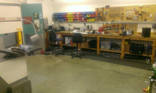
Perfactory 3D printing test trial 2

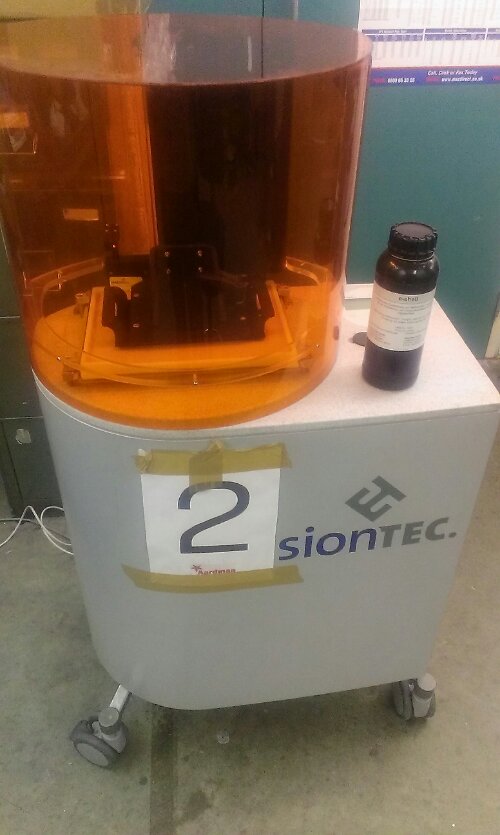
So setting of the 3d printer we had two models 1 was a dodecahedron, the other was a spare, the dodecahedron was a model that contain another dodecahedron inside each other suspended in mid air. This was unknown at the time however. Adding both files to the magics software and creating a job to import into perfactory 3D we got the machine off running using pink material.

image

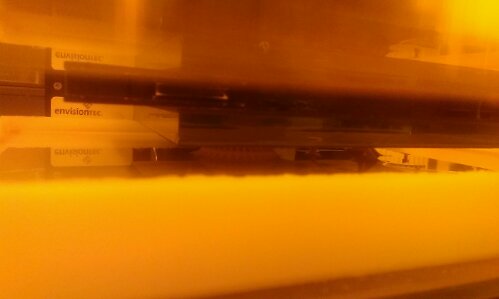
Here you can see about 10 millimetres of the model has been printed and is sticking out of the vat of resin. This is about an hour into the print the total print time is 4 hours.

image

This picture you can see the dodecahedron peeking out the bottom there is no dodecahedron that he done inside this is because the model was constructed without support material meaning of the internal parts will not supported . This means the currently the central internal model resting inside may be picked up later on during the print process later today. However although this part will be a failure the sphere is turning out nicely which should resulting in a clean sphere. We have to wait another 3 hours to see the final outcome.

(note post was spoken and reedited so may seem a bit odd reading)

Posted from WordPress for Android

3D printing at work DLP style

So, been working on setting up some 3D DLP printers at work which were used to print mouths for Pirates!, and discussing with suppliers of the machines abd another company, I have now located licences and software to run them.

Software is Perfactory RP 2.9 by EnvisionTec, suppliers of the Perfactory DDP printers.
Magics 13 by Materialise.

So after running and setting up the machines I got one connected and printing z test part.

I have not calibrated it, and I’m using out of date (by 1.5/2 years) so we will try and see what happens…

image

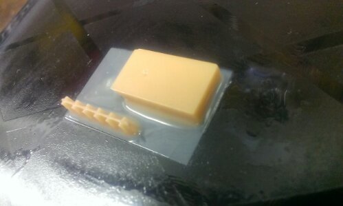
Finished 4mm print, stopped due to end of work hour’s
image

image

Posted from WordPress for Android
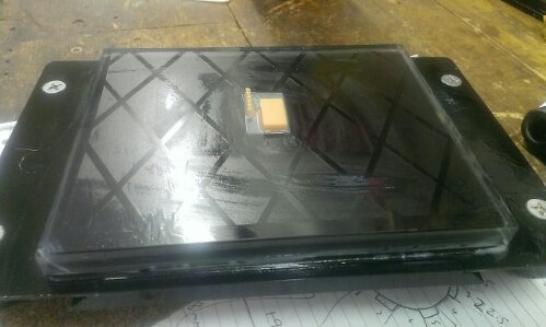
Thermal inserts for 3d printed parts

So, a project of mine requires me to screw a lid into a 3d printed chasis, and make it secure!

The mnost common thing to do is to just drill and tap into the plastic part to give it the screw thread in which to screw into.

There are several issues, A its weak. drilling into an object with a low infill ratio will mean there is no material around after you have drilled into the first few top layers meaning it only will give 1 thread. Not much!

To overcome this, you can up the fill, or print a hole inwhich to tap, and give it additional perimeters so it makes it solid around the thread. again this is better,but we rely on plastic threads to grip into.

Lets take a look at those examples used in industry. Thermal injection to be precise.

When putting a thread into a plastic part, the best way is to add a brass threaded insert. These are small threaded nuts with a grippy outside which is placed into a mould tool before plastic infection. They remain fitted to the plastic due to the burrs on the outside edge, but give a brass heavy duty thread on the inside.


These are cheap, well about £50 for 100, 50p each is the cheapest through a company, ebay sell 100 for about £13.50?

Brass insert fastener

These are used ofetn for parts, including the plastic/glass fibre arms for my quadcopter.


When it comes to 3D printing, we are unable to print around these inserts, therefore another insertion method is needed.

Firstly we need to print a hole for the brass insert to fit into. This gives the surrounding purchasing for the fitting to fit into.

Then we place an insert onto the tip of a soldering iron, so the iron heats the insert.

Then using the iron, push the brass insert into the plastic hole, so the plastic melts around the insert.

Removing the soldering iron allows the insert and plastic to cool, leaving you with a brass insert thermally welded into your plastic part.

I just need to get hold of some thermal inserts!

Check out this video for more info…

http://youtu.be/iGNXHWPFAKo

Hole size recommendations pdf is available here: http://www.axisproto.com/pdf/spec_inserts_EN.pdf

Animoko head,

So I have a new job! Well I have done for number of months, since November, and I’m loving it. I am Mechanical Engineer at Aardman Features Shaun the Sheep ltd. Working on the new Shaun the sheep movie.

Some tasks I have been working on include overhauling the MILO motion control robots, from a company called Mark Roberts Motion Control. Redesigning a focus motor using Nena 8 steppers, and generally designing, nodding and helping out Art department with metalwork requirements.

My current proje t is redesigning the heads for the Animoko motion control platforms, again from Mark Roberts.

This is required as currently it is awkward to fir the camera onto the head without having to use a secondary heavy motion control platform ‘rotate’.

This new bracket will allow the camera and sliding base plate to sit nicely direct, whilst keeping it all nodal.

Here are some pics of progress…

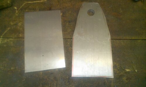
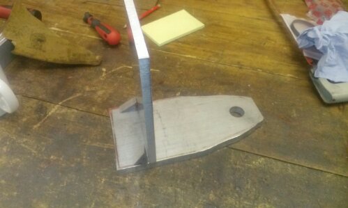
Rough plates

image

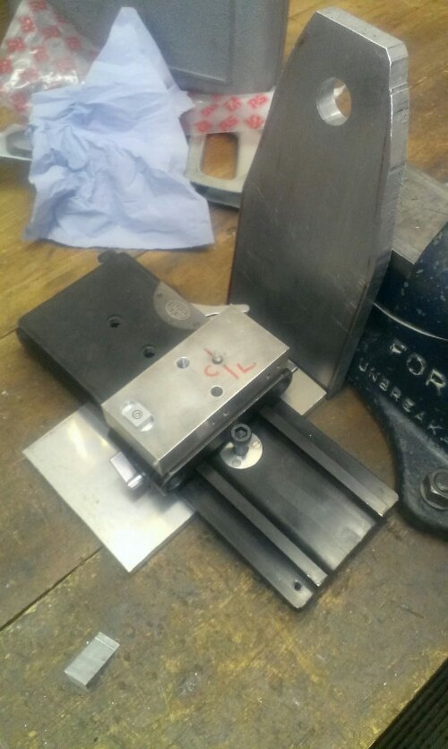
Basic mock up

image

Sliding base plate shown

image

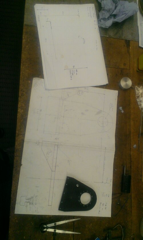
Workings out and drawing on paper, by Lew.

image

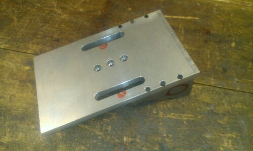
Base plate machines to size and slots added to allow for future use with other campers, note side bits fitted. Central holes to allow direct camera mounting shoudld that be required.

image

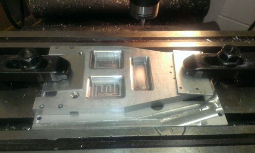
Rear of top part with slit, mounting holes and pockets to reduce weight, shown fresh from milling machine.

image

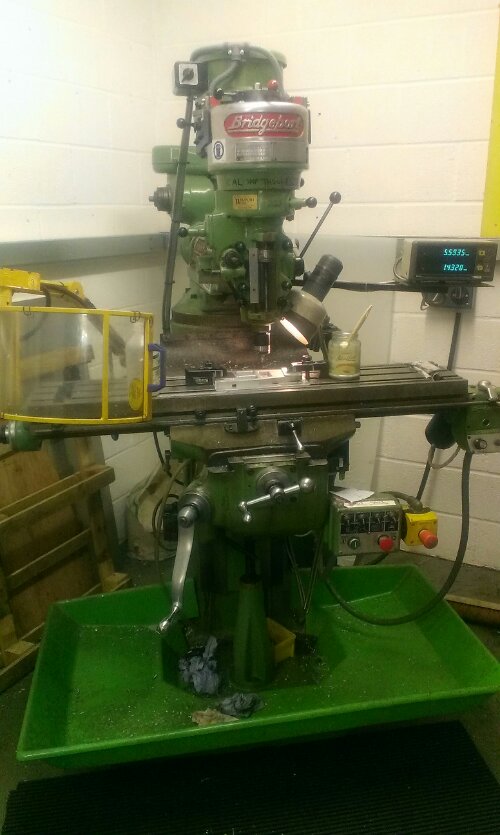
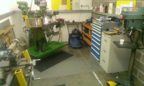
The milling machine, and workshop, lathe etc

image

image

image

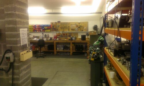
Below is the shadow board and Myford ML7-R lathe

image

Startrite 20v bandsaw

image

Posted from WordPress for Android