
Author Archives: npoate
Settings for prusa
Just on break, and worked out accurate settings to solve excess plastic going into the extruder, New settings for ex stepper was 700, New are 630 steps per mm
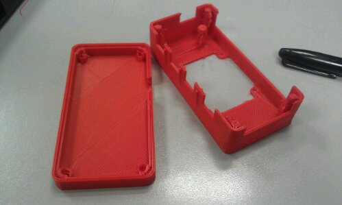
Pla reprap prusa issues
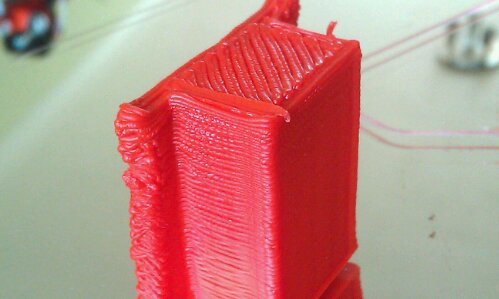
Trying this version of the prusa, my new red model, featuring prusa 2 parts, I am printing running slic3r 0.9.2 and am having funny print results, the parts are somewhat blobby
Not sure what is causing this, could it be I have moisture in my pla? I hope not! I don’t keep it in a box with decad stuff, but I thought it’s ok on my makerbot… Anyway, I’m having a few issues so I need to work on the settings still
However on positive note, I tried the new dual print separate print commends on slic3r, looks good!
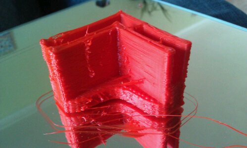
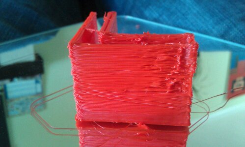
A note, before I printed these u tried a motor housing, excess plastic in corners and odd stepping in the plastic straight lines… Hmmmmmm
Not sure about that either, any ideas?
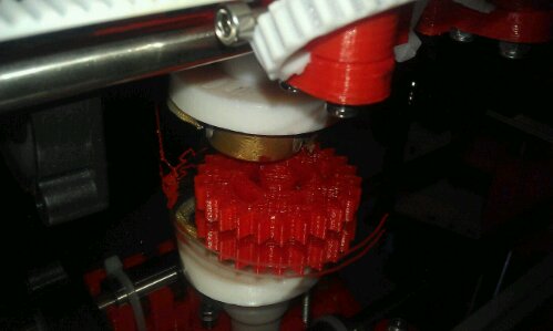
Printing tantillus extruder gear
Pla bed belt mounts
Turns out my prusa heat bed mounted directly to the MDF board on my Y axis is heating the pla belt
mounts causing them to melt slightly ans loose grip of the belt. Major issues. Should I mount the bed on standoffs?
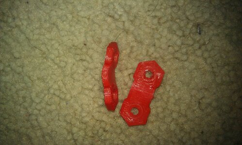
Quick solution… Make some from aluminum
It Lives
Welcome to my new site, hosted by an awesome chap 🙂
It will take a few days to get used to how this site works and for me to populate it, so… well no one will read this so, we shall take a look at all its functions 🙂
Reversal settings for skeinforge.
Well, i have finally got my stepper extruder working! With some help from IRC and friends, i have finally made the pololu PCB – a one sided design which has a single wire on the top board.
connecting it to gen 3 makerbot mobo it works straight off the hat with x y and z axis, so for this i am really please, however for the extruder it took a bit of bodging with firmware and machines to get it to work. Turned out that the thing was a problem with repg 25, but i seem to have it working now after adjusting the various settings and maybe a loose connection or 2.
so anyways, the PCB is:
building of wobble arrester and new cable
Well its been an eventfull couple of weeks.
firtly i decieded to change my usb ttl adapter for the makerbot to a 5v logic level, as apposed tothe 3.3v logic level one i was using. the idea behind this was that the switchover signal voltage could have been too low and therefore meant the data was not being sent at good quality. I was annoyed when i bought the first cable, as i was thinking it was a 5v level cable, but alas… oh well.
the first tests came as i was setting up the uni makerbot for a demo of high calibre… more on that in a sec, but i managed to start repg and the new software version, meaning i could import and manipulate the files stl etc in repg.
the first trial pieces were done using my pc desktop, an old pentium 4. (i now bought a i5 HP laptop, so yay!) I did wounder if the processing speed was too slow for the makerbot, and i think i might have been right…
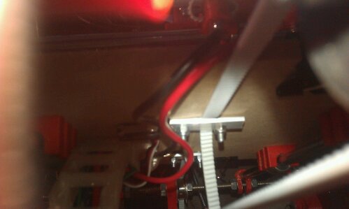
anyway, my first prints using the 5v cable, turned out to be good. they were a corner bracket, to try simple shapes… and then the z wobble arrester. this is an amazing thing an im glad i printed it, as my sides are virtually wobble free (need a second one for other side of rear as that too is a bit wobbly…
anyhow, i printed these with great success, installed the wob arr and set to print something more complex. The gear set, recently uploaded seemd lie the perfetc vhoice.
link here :(insert link)
the results seemed ok, but the thinner smaller gear had to be height adjusted as too much plastic was comming out causing lumps. – this maybe because there wasnt enough time to cool befre the heater nozel came ploughing through, so need to work on ‘cool’ settings as mentioned in recent blog post elsewhere – should really write the links down!. need to adjust speed and extruder flow rate too, both adjust this issue.
right a picture…
or 2…
the L bracket, shows several wobbly edges so off to print the z wobble arrester…
the wobble arrested whilst printing

The wobble arrester works wonders, and if anyone needs to see why it is handy, check this video out of the one i installed…
with the wobble arrester installed, i made the gears.
picture too come.
Motors and comms test
Comms test working, now transmits the tilt sensors data, however i need to sleep the xbee as it is draining power from batteries so rest of circuit is not working as well, also this is due to the fact i am running it through a 5v reg with 4.5v batteries, not the 9v i was in the previous design.
I have also recieved a fone call from technobots reguarding the motors, they are now instock and are sending them today to arrive tomorrow, so now i have some motors – G8 Solarrobotics motors and associated 2.5cm diameter wheels.
http://www.technobots.co.uk/acatalog/Online_Catalogue_Solarbotics_Geared_Motors_81.html
meeting today, and still looking for dan 😀
PCB and components update
PCB have arrived fromt he states. They have allready got the usb – serial chip added, therefore all i need to do is purchase the rest of the cmponents, wjhich i have just done, i require:
2.7k resistor, low current T-1 led, 10uF and 0.1uF caps
to make up 2 boards, i got…
2.7k resistors x 2
2x ceramic capacitors
2x electrorolytic radial caps
2x yellow low current led
2x panel clips for leds
the usb socket i got was from farnell, and cost over a pound but comes with a molex style connector on it, therefore i have bought some molex 90 degree angled connector blocks to attach them to it.
i will be heading to maplins to get a box to fit these into it, so shall require a few pcb spacers to attach it to the box. im thinkin gof using plastic ones as i can cut these down easily.
the pcb header strip 2mm are still not arriving yet due to uni postage issues with payment, therefore i will try them tomorrow, i shall therefore make the rest of the board up tonight, and try to see if the drivers work.
that and my other coursework lol.
With this pcb working, we can test the board with a mac and the rest of the pcb can be nmade for the outer ball, then can be placed inside a ball, for testing.
The motor drive circuit i shall get a final copy of tomorrow from the robot football club, so shall have that ready to be made next week.