Dust cover build for camera lens tester

Today’s task is to machine a bullet of aluminum into a lens cover for the lens testing equipment.

Lathe to turn down t the lender basic shape and then a dividing head will be used to machine the tabs which are used to security in place.

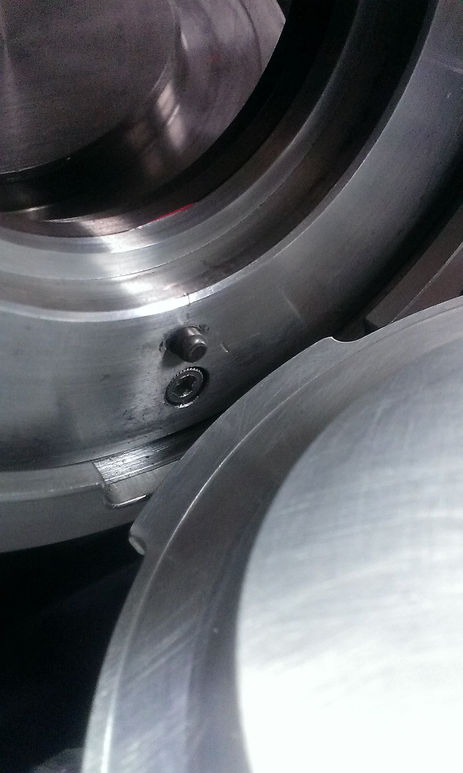
Hello is a picture of a lens mounting a piece used to fit a standard camera lens to a lens test equipment. He you can clearly see before tabs which i use to lock the mount in place.

image

The restaurant has been drawn up to show the part i need to make. Parties to the machine from 3.5 inch tablet approximately 2 inches wide . This will feature the tab fixing brackets and a half inch diameter knurled handle.

First lady of malaysia news russian ballet . First lathe operations are within tolerance of -0.001+0 inch.

image

image

The next operation sis to mount the part 12 the dividing head on a mail and using a 3/16th cutter, mill the 4 tabs.

image

Clocking the milling machines we make everything central. we can fit a cutter and start making the tabs. The tabs need to reduce radius by 0.13 inch.

FinalĀ  tabs milled. All I need to do is sand down the edges using 1200 grit paper and to test fit. I also need to do the knurling on the handle.

image


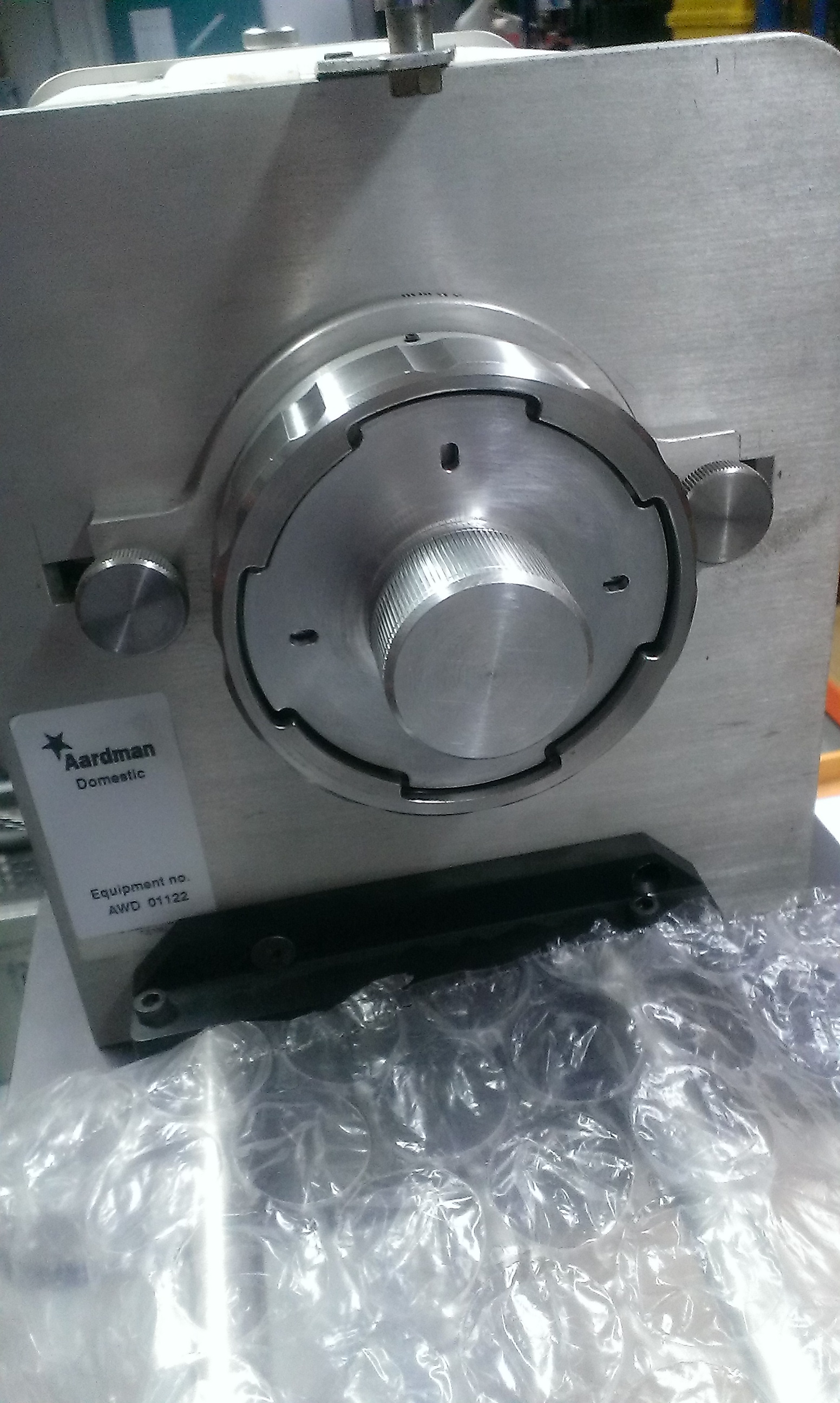
A quick sanding of the edges to remove the burrs gives us a time to test fit into the machine.2014-05-20 14.55.392014-05-20 14.55.43


Rats, it doesnt fit there is a small pip which is used to locate the mounts into place. I think i need to add these in, but as it can be fitted in 4 orientations, i need to add 4 holes!

Back to the dividing head, this time, i need to rotate the handle 10 times – 10 into 40 go 4 times, and as we need 4, i can place it.

Carefully aligning it up so that the pip hole is in the centre of the tabs, and a slot is milled at the correct distance, we can mill using a 3/16 cutter.
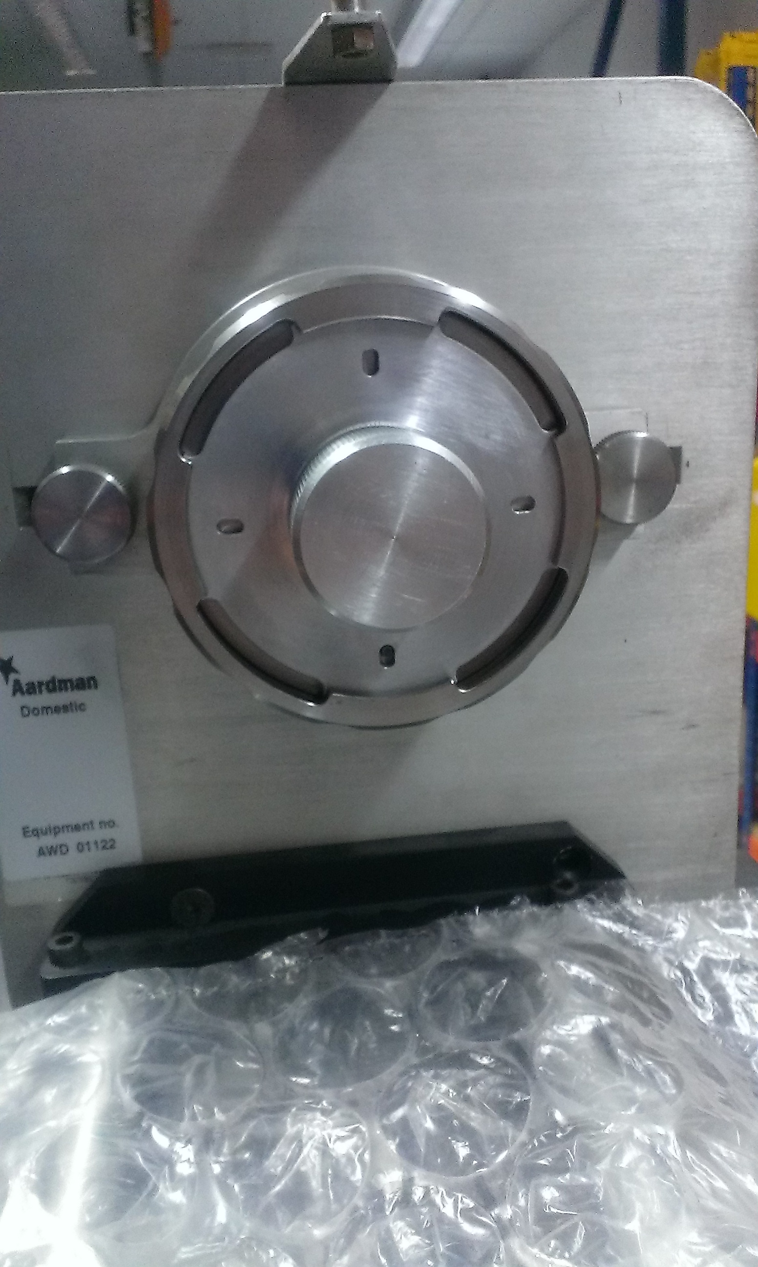
Now to test fit!

2014-05-20 15.35.262014-05-20 15.35.46

Perfect! and it even fits in place once the cap is screwed!

2014-05-20 15.35.56


JOB DONE!

Milling tool rack

So, after a few months at Aardman, I have accumulated a number of end mills, which are rolling about the tray, which… is not the best, as any slight nick on the cutting edges can result in ugly surfaces – yes end mills are to cut side on! not really for plunging at ends, but we all do that anyway!
So I have about 12 or 10 cutters which I have tried to restrain usingcloths, wooden disks etc but each time the drawer is opened and closed they rattle loose…

IMAG7572

So, I decieded to mill out a ‘cutlery drawer’ style thing for them, you know the ones with slots to hold knives, forks, spoons, and that garlic crushed insert full of bits of old garlic that the spikey brush just can’t remove… Anyways you know.

So I got a bit of plywood 3/4inch thick, and roughly draw a few marks on it in the shape of slots that could hold my cutters, just to give an idea.

image

image

I wanted a selection of sizes of slots so I picked the medium sized cutter I had, I think that was 5/8th or 3/4, tho I think it was the first, I clamped down the plywood and set up the cutter at the first roughly drawn slot.

Powering on the milling machine I made my fiirst cut to a depth of 350 thousandths and cut a series of slots, I got 6 slots horizontal about 3inches long which fitted my smaller cutters.

image

The next set of slots are made wider by running the cutter offset from the first slot, again leaving a small edge between slots, this gave me again 6 slots by starting closer to the edges.

The final 3rd of wood is made into longer wider vertical slots to house 1 inch and 3/4 cutters, 3 slots are given. All this milling creates a lot of sawdust… time for a vacuuming!

image

image

Removing the wood from the machine revealed lots of splinters on the edges of the top of the slots. A bit of sanding down and all done!

image

image

Large cutter doesn’t fit! Oh no! So a quick chiseling….

image

All done! Tidy drawers!


Antweight motor control – Baby-O

From: http://garya.org.uk/software/embedded-c/antweight-speed-controller

/*
 * SpeedController.c
 *
 *  Created on: 19 Aug 2013
 *      Author: Gary Aylward
 *   Copyright: Gary Aylward, 2013
 *     Website: http://garya.org.uk
 *     License: Creative Commons BY-SA 3.0
 *
 *     http://creativecommons.org/licenses/by-sa/3.0/
 *
 *     Pololu Orangutan library (c) Pololu Corporation, licensed under CC-BY-SA 3.0
 *
 *     1.0 19/08/2013 Original release
 *     1.1 25/08/2013 Fixed battery monitor filter bug
 */

/*
 * Antweight R/C speed controller using Pololu Baby Orangutan board
 *
 * Set linker to use pololu_atmega328p library.
 *
 * Module pinouts are defined below, the settings used allow other pins to be used for
 * further R/C channels, extra PWM outputs, UART etc.
 * The battery voltage is fed to the ADC via a potential divider so that the ADC sees
 * the voltage of a single cell. If the under-voltage lockout is not required, connect
 * the ADC input to Vcc or redefine dCELL_MV below.
 *
 * Mixing is set up for an R/C transmitter with the following characteristics:
 * Channel 1 = Left/Right, Right = longer pulses
 * Channel 2 = Forwards/Reverse, Reverse = longer pulses
 *
 * Motors are connected with +ve terminal connected to M1B / M2B, -ve to M1A / M2A
 * Motors turn clockwise (when viewed from shaft end) with positive voltage
 */

#include <pololu/orangutan.h>

#ifndef F_CPU
#define F_CPU	20000000	// Baby Orangutan runs at 20MHz
#endif

#define dCHANNEL1	IO_C0	// R/C Ch1 input pin
#define dCHANNEL2	IO_C1	// R/C Ch2 input pin
#define	dLED		IO_D1	// LED output pin
#define dADC_CHANNEL	6	// ADC battery monitor channel

#define dZERO		1500	// Nominal pulse width
#define dMAX		2000	// Max pulse width
#define dMIN		1000	// Min pulse width
#define dMAX_PULSE	2200	// Pulse width for error detection
#define dMIN_PULSE	800		// Pulse width for error detection
#define dTIMEOUT	30000	// 30ms timeout on R/C pulses
#define dMAX_SPEED	250		// Max speed setting
#define dMIN_SPEED	-250	// Min speed setting

#define dFILTER_SIZE	600	// Length of under-voltage detection filter, 6 steps per ms
#define dCELL_MV	2750	// Minimum cell voltage in mV


int main()
{
	unsigned int vVoltage = 0;			// Battery cell voltage measurement
	unsigned char vUnderVolt = 0;		// Under-voltage error flag
	unsigned long vFilter = 0;			// Under-voltage filter counter
	struct PulseInputStruct vPulseInfo;	// Orangutan library pulse structure
	unsigned long vPulseLength = 0;		// Pulse length in ticks
	unsigned char vState = 0;			// Current pulse state
	unsigned long vPulseCh1 = dZERO;	// Channel 1 pulse in ms
	unsigned long vPulseCh2 = dZERO;	// Channel 2 pulse in ms
	int vLeftSpeed;						// Left motor speed
	int vRightSpeed;					// Right motor speed
	unsigned char vError = 1;			// Error flag

	// Configure pins as pulse input channels
	pulse_in_start((unsigned char[]) {dCHANNEL1, dCHANNEL2}, 2);
	// Enable internal pull-ups on R/C input channels
	set_digital_input(dCHANNEL1, PULL_UP_ENABLED);
	set_digital_input(dCHANNEL2, PULL_UP_ENABLED);
	// Initialise LED to off
	set_digital_output(dLED, 0);
	//Set ADC to 10-bit mode
	set_analog_mode(MODE_10_BIT);

	while(1)
	{
		if (analog_is_converting() == 0)
		{
			// Start a new conversion if one isn't already running
			start_analog_conversion(dADC_CHANNEL);
		}
		// Get time since last edge on R/C channel 1
		get_current_pulse_state(0, &vPulseLength, &vState);
		if (pulse_to_microseconds(vPulseLength) >= dTIMEOUT)
		{
			vError = 1; // R/C timeout - signal lost
		}
		else
		{
			get_pulse_info(0, &vPulseInfo); // get pulse info for R/C channel 1
			if (vPulseInfo.newPulse & HIGH_PULSE)
			{
				vPulseCh1 = pulse_to_microseconds(vPulseInfo.lastHighPulse);
				if ((vPulseCh1 > dMAX_PULSE) || (vPulseCh1 < dMIN_PULSE))
				{
					vError = 1;	// Pulse is too long or too short
				}
				else
				{
					vError = 0;
					if (vPulseCh1 > dMAX)
					{
						vPulseCh1 = dMAX;
					}
					if (vPulseCh1 < dMIN)
					{
						vPulseCh1 = dMIN;
					}
				}
			}
		}
		// Get time since last edge on R/C channel 2
		get_current_pulse_state(1, &vPulseLength, &vState);
		if (pulse_to_microseconds(vPulseLength) >= dTIMEOUT)
		{
			vError = 1;	// R/C timeout - signal lost
		}
		else
		{
			get_pulse_info(1, &vPulseInfo); // get pulse info for R/C channel 2
			if (vPulseInfo.newPulse & HIGH_PULSE)
			{
				vPulseCh2 = pulse_to_microseconds(vPulseInfo.lastHighPulse);
				if ((vPulseCh2 > dMAX_PULSE) || (vPulseCh2 < dMIN_PULSE))
				{
					vError = 1;	// Pulse is too long or too short
				}
				else
				{
					vError = 0;
					if (vPulseCh2 > dMAX)
					{
						vPulseCh2 = dMAX;
					}
					if (vPulseCh2 < dMIN)
					{
						vPulseCh2 = dMIN;
					}
				}
			}
		}
		if (analog_is_converting() == 0)
		{
			// If ADC conversion is finished, check the battery voltage
			vVoltage = analog_conversion_result_millivolts();
			if (vVoltage < dCELL_MV)
			{
				if (vFilter >= dFILTER_SIZE)
				{
					// Filter has timed out, leave the fault flag set
					vFilter = dFILTER_SIZE;	// Prevent filter count from overflowing
					vUnderVolt = 1;	// Set fault flag
				}
				else
				{
					vFilter++;	// Increment filter count
					vUnderVolt = 0;	// Clear fault flag
				}
			}
			else
			{
				vFilter = 0;	// Reset filter if voltage is above limit
			}
		}
		// Calculate motor speeds
		vLeftSpeed = ((vPulseCh2 - dZERO) - (vPulseCh1 - dZERO)) / 2;
		vRightSpeed = (-(vPulseCh2 - dZERO) - (vPulseCh1 - dZERO)) / 2;
		// Limit maximum speeds
		if (vLeftSpeed > dMAX_SPEED)
		{
			vLeftSpeed = dMAX_SPEED;
		}
		else if (vLeftSpeed < dMIN_SPEED)
		{
			vLeftSpeed = dMIN_SPEED;
		}
		if (vRightSpeed > dMAX_SPEED)
		{
			vRightSpeed = dMAX_SPEED;
		}
		else if (vRightSpeed < dMIN_SPEED)
		{
			vRightSpeed = dMIN_SPEED;
		}
		if ((vUnderVolt == 1) || (vError == 1))
		{
			// Stop motors and light LED if a fault exists
			set_m1_speed(0);
			set_m2_speed(0);
			set_digital_output(dLED, 1);
		}
		else
		{
			// Set motor speeds and turn off LED
			set_m1_speed(vLeftSpeed);
			set_m2_speed(vRightSpeed);
			set_digital_output(dLED, 0);
		}
	}
}